3dMax Object Creation TutorialWritten by Schwaa
I will not go into great detail on how to run 3D Studio Max or Photoshop. You should be
familiar with the basics of these programs before you start. I will however explain a few
parts of the programs that I use to model. These aren't nescessarily the best ways to model,
just how I prefer to do it.
|
||
Part One: Familiarizing with 3D Studio MaxFirst open 3D Max. Choose objects from the top tool bar {Fig.1} and select a cube, drag in the window to create your cube, doesn't matter how big, we'll deal with that later. Also left click on the name of the view you're working on (yellow arrow in Fig.1) and from the pull-down menu choose shaded and edged faces. You don't have to do this, it just makes it easier to see what you're working with. Now go to the side tool bar and select modifiers{Fig.2}. Now click on More... {Fig.3} which will bring up a list, from this list choose Edit Mesh You have turned the cube into an editable mesh, now we can modify it! You'll notice that the side tool bar says Edit Mesh instead of box 01 now. Below Edit Mesh there is a selection bar which houses 5 symbols {Fig.4}, these are very important. We will use Vertices heavily with Faces and Polygons coming in second. Edges are used a little bit, and Objects will rarely be used. With the cube selected, choose Vertices {Fig.4} and you'll see the vertices of the cube light up, now we can change the shape of the cube, select the move arrow {Fig.4} under Main Toolbar {Fig.1}, click one single vertice and move it around. Doesn't look like a cube anymore does it? Hit Ctrl-Z to go back a step so you'll have a cube again. Now we'll do something different. All that we're doing now is establishing creation parameters that I use so this tut will be easier to follow. So please don't get bored. This time go back to box {fig.5} in the side toolbar (drop down menu in modifier stack), click OK when the warning box comes up (be careful with highly detailed models though). Change the box length, width and hieght sections to 2. This will split the box into 4 polygons per side giving us more options for deformation. In the modifier stack, scroll up in the drop down to Edit Mesh again, this time choose Polygon {Fig.6} instead of vertices and select one polygon on the cube. Now scroll down the modifier stack and click Extrude {Fig.7}. Hit the up arrow or punch in a number (if you do it twice you'll create two seperate extrusions). You should have a cube with a cube sticking out of it now. Click on another polygon now and hit delete {Fig.8} on your keyboard. Now you'll have a empty square on the side of your cube. "But I don't want a hole on my cube!" you say? OK, we'll fix it then (you could Ctrl-Z to backup but that's not the point). What we want is to actually create a polygon.
Now look under Edit Geometry in the modifier stack. Choose Create {Fig.9} (with polygon selected).
To create a polygon you must click on all the vertices that you want the polygon to be created out of in a counter
clockwise rotation, finishing with the first one (5 clicks to make a 4 sided polygon)(counter clockwise will create a face looking towards you, clockwise
will create a back facing face). You cannot see the backside of a face so you probably don't want to create in a clockwise
direction. So far we've covered creating an object, turning it into an Editable Mesh, extruding faces, and face creation. One last thing to cover and that is welding vertices. This comes in handy when connecting objects together and also when modifing objects. To Weld Vertices you'll have to have vertices on the edge of an object. We'll choose polygons again and select the face that you have extruded. Delete it so that you have an open space surrounded by 4 individual vertices (delete the red [selected] polygon in Fig.7). Now select vertices in the side toolbar and select these 4 vertices one at a time and pull them to the center of the open space {Fig.10}. When they are all close together Ctrl-Click each seperately or drag the cursor to chose them all (be careful that you don't select vertices on the other side of the cube). We are going to weld these vertices together so you'll have a pyramid on top of the box. Scroll down the side toolbar until you see Weld.
In the Weld box pick a number to type in next to Selected.
The closer your vertices are together the smaller the number you can use (like 1.0). It's more accurate to use smaller numbers.
With the number entered, click Select and the vertices should join, if you get an error (no vertices in range) then you'll have to increase
the number.
|
|
|
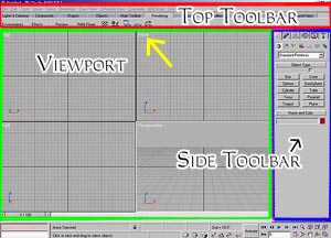
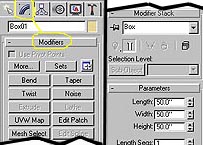
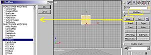
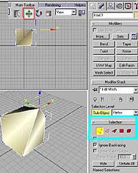
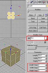
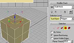
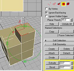
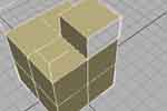 Fig.8 |
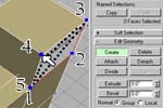 Fig.9 |
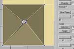 Fig.10 |
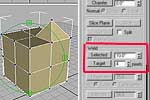 Fig.11 |