Importing Meshes from 3DS Max into Dromed (Thief II) by Schwaa
Thanks go out to Shadowspawn and Colourless for helping me figure this stuff out :)
Section one:
Setting up a mesh with Joints and Planes (this section is not about getting high in anyway whatsoever ;)
SwordsMan
BowMan
Bystander
Zombie
Burrick
Robot
Section two:
Importing the mesh, file types, ect...
Section three:
Problem solving.
Section One - Mesh Joints and Planes
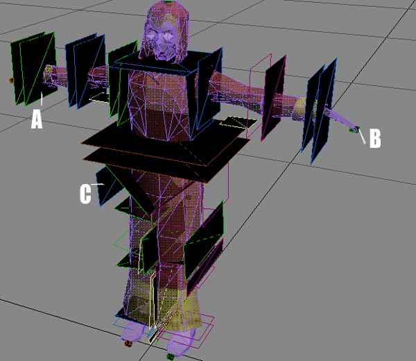
{Fig.1a}
An explanation of joints and planes in {Fig.1a}
This limit plane describes one of the edges of joint rotation, any vertices/polys inside the space between these two planes will become "stretchy polys" and will flex in Dromed during animation. There is a small square "Joint" between these planes, anything falling outside these planes will not move when the wrist flexes.
X= tells Dromed to not render, it won't be seen in game.
JR= "Joint Right"
WR= "Wrist Right"
SR= "Shoulder Right"
EL= "Elbow" - These last two place the plane on a "Torso"
J= tells Dromed to not render, it won't be seen in game.
LFINGER= "Left Finger"
X= Not Rendered
JRHI= "Joint Right Hip" - You'll notice that this plane is beside the AI and not thru a joint area. There are several of these per mesh and they serve a very useful purpose. The stop the limit planes of the joints from extending to infinity. But mainly they stop problems from one joint crossing over the planes of another, basically just letting an AI retain its shape. More noticable is a swordsman mesh that has a large plane under the right arm, this keeps the sword from being bent along with the knee when the AI's arms are down.
One thing to keep an eye out for is correct joint and limit plane names, they tend to get shuffled when converting them from an RTG file into a 3ds file.
Section Two - Importing the mesh, file types.
{Fig.1b}
Conversion Tools
There are multiple tools that come with Thief II and a few that have been created
that allow you to convert 3ds files into Thief formats, they are:
These tools can all be found in your ThiefII/RES/obj and ThiefII/RES/mesh folders, with a few exceptions which can either be found on my downloads page or Shadowspawns site.
Place them into the folder you are using for custom objects/meshes.
DOS Prompt - All of the conversion programs run through a DOS Prompt. The easiest way
to do this is to find your DOS Prompt. In Windows ME it can be found in the C:\WINDOWS folder. I
believe it is in the same place on an Windows XP system. Right-click and made a shortcut to it, place this shortcut
in your custom objects folder.
Now when you use any of the tools listed below you will just double-click the DOS shortcut which should have the path
of the folder it's in typed and waiting, it should look something like this:
C:\Custom Objects>
You will type the following commands in for each specific program.
RTG Files - This is the original LGS mesh file, it can be found in your ThiefII/RES/Mesh
folder. This file will have NO extension unlike .bin, .e and .cal files. If you want to use the joints for Zombie 01
find zom01 (no extension) rtg file. This isn't a nessecary step, the above .3ds files have already been converted.
The Dos command would be:
rtgto3ds zom01
Now you will have zom01.3ds.
3ds Files - To convert 3ds files they need to be UV mapped. If you source the files from somewhere and you're not sure, you can import them into one of the mentioned programs and check it. If you don't have a program for it (Anim8tor is FREE) then you can try converting it into a .bin anyway. You'll probably create an .E file but when you go to convert it into a .bin you'll find out if it'll work or not.
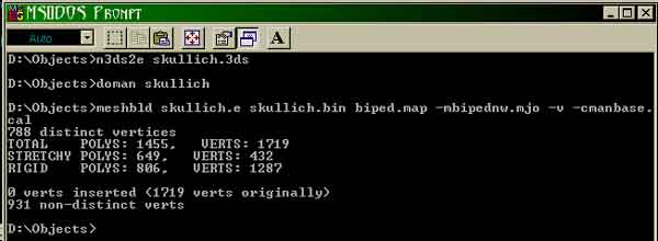
To convert a .3ds file into an .e file type this in the DOS window:
n3ds2e zom01.3ds
Now you should have a file named zom01.e in your custom object folder. If you recieved an error look at the
problem solving section.
E Files - need to be converted into a .bin AND .cal to be used as an AI.
An AI has joints and motions, therefore you will need the additional .cal file. The .bin file tells Dromed what shape,
color and mapping an object or mesh has, the .cal file tells it where the joints are and how they move. This is why an
AI will "collapse" in Dromed if no .cal file exists.
To create a .cal file you will need to have .map and .mjo files for the AI you are using.
Map and MJO files - These files can be found in the Thief/RES/Mesh folder. Their
names correspond to the type of AI with which they are associated. For example, I have been using zom01 for this tut. That's
Zombie 01, zombies are Bipeds (walk on two feet) so you'll need to find biped.map and biped.mjo
and put them in the same folder as your custom objects too. Map and MJO files can be read in Thief Edit or
Notepad, open them up just for kicks.
MAP will have a number for each joint, this can be helpful if you want to
give the AI a Creature Attachment like SFX particles, wings or a tail using that joints number.
MJO will show you the number of Torsos on an AI and which limbs they contain. Basically a Biped has two torsos. One holds
the head and arms, on contains the legs. This would probably be more helpful if motions could be made.
Other AI files will use different map and mjo's. For example: Playarm is the players arm, it is used for the players
hand holding a sword or blackjack. Spidey for spiders, Flexbow for the players bow and arrow.
Along with the.map and .mjo files you will need to include manbase.cal (also in Thief II/RES/Mesh) and the correct
DO.bat files in you custom objects folder.
DO.bat files - These tools run meshbuild from DOS. To use them you will first need to right click on them and choose edit, remove the bold lines below, but leave the italics:
@echo off
echo.
n:\bin\win95\rtg2e %1 %1.e
n:\bin\win95\meshbld %1.e %1.bin biped.map -mbipednw.mjo -v -cmanbase.cal
echo.
Now it will say:
meshbld %1.e %1.bin biped.map -mbipednw.mjo -v -cmanbase.cal
Save and it is ready to use. Basically it says "run meshbuild, size = 1% ,e to 1% .bin (same size input to output files),
use biped.map and .mjo along with manbase.cal". I'm not sure what the -v means.
Now that you have all of the files in place and edited correctly you can convert your .e file into a .bin and .cal. Type
this into the DOS Prompt:
doman zom01
No need to type .e after zom01, meshbuild is already looking for an .e file, it also knows to export a .bin and .cal.
If everything goes well you should have a .bin and .cal in your custom object folder.
It's now time to import the AI into Thief :)
Importing Mesh Files into Dromed
Now you have a zom01.bin and zom01.cal file, place them in Thief2\Mesh folder. Place the texture(s) into Thief II/Mesh/Txt16 folder.
Open the object hiearchy>animals> and choose which hiearchy you want to create your new AI under, pick the closest
possible AI and hit ADD. In this case we would start under Undead>Zombies. Give your new model a specific name. Edit as
nessecary in Dromed and create in the physical world and see if it works :)
If you create a new type of AI don't forget to save your gamesys and mission in Dromed, or just create a regular AI
and change the Shape/Model Name and put your new name in the text feild.
Congragulations! You have successfly imported a new lifeform into the Thief Universe, if you haven't head on down to the Problem solving section...
Section Three - Problem Solving
Common errors that show up in the DOS Prompt:
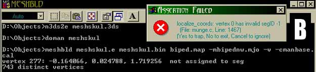
Pic B is the error you will recieve if any vertices are out of bounds. The DOS Prompt will usually kick out 3-10
vertice numbers before it crashes. In 3DMax you can select single vertices and look in the selection column for the
number, however this has always been tedious for me trying to track down 1 vertice out of 1,000. But if you keep the DOS
Prompt on screen you can use the coords from the DOS Prompt to your advantage. I always keep my 3D program running during
conversion in case I have to go back and fix anything, then I will create a small cube and name it something like
"Delete_Me" as a reminder to myself that it isn't a joint.
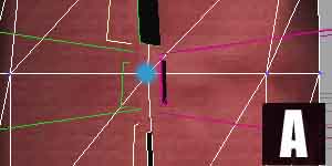
OK, now you have a cube named Delete_Me in 3d with your mesh, choose the Move tool in 3dMax. Right click on
the Move tool button now and it will bring up a coords. window, type in the coords (see DOS Prompt) and hit enter:
-0.165
0.024
1.179
This will move "Delete_Me" the cube to the same position as the bad vertice. Now you need to find the offending
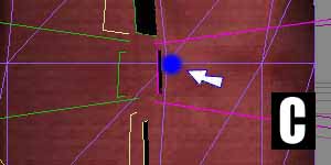
vertice and move it to a better location. In this case a vertice (Pic A) fell in between the two knee joints, the
fix is to nudge it over into one of the knee joints (Pic C). If you had more than one error continue until they
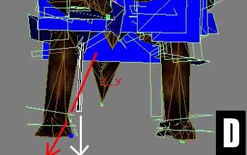
are all fixed. Another associated error is having a joint plane at an angle that will clip off vertices, in this
case you need to fix the clipping planes position instead (Pic D). This is a Burrick's leg, the Red Line is where
the plane was,cutting off the Blue Vertice. The White Line is the correction made.
Common errors that show up in Dromed: